Introduction
Mullvad is an excellent VPN provider with a privacy policy that respects the customer. It allows you to mask your public IP address, information which can be used to identify you, track you, and advertise to you. Masking your public IP address is an important first step in taking back control over your digital life and hiding yourself from invasive “tech” (read: advertising) companies, as well as the likely invasive privacy policy of your ISP. However, Mullvad limits you to five devices per account. What do you do if you want to tunnel more devices through Mullvad’s servers for privacy reasons or you want to force IOT devices or others that do not support Mullvad’s app through a VPN? Why not setup a whole home VPN by configuring a WireGuard tunnel to Mullvad on your OPNsense firewall? In this guide I will show you how to accomplish that – it’s easy and fast.
Instance Configuration
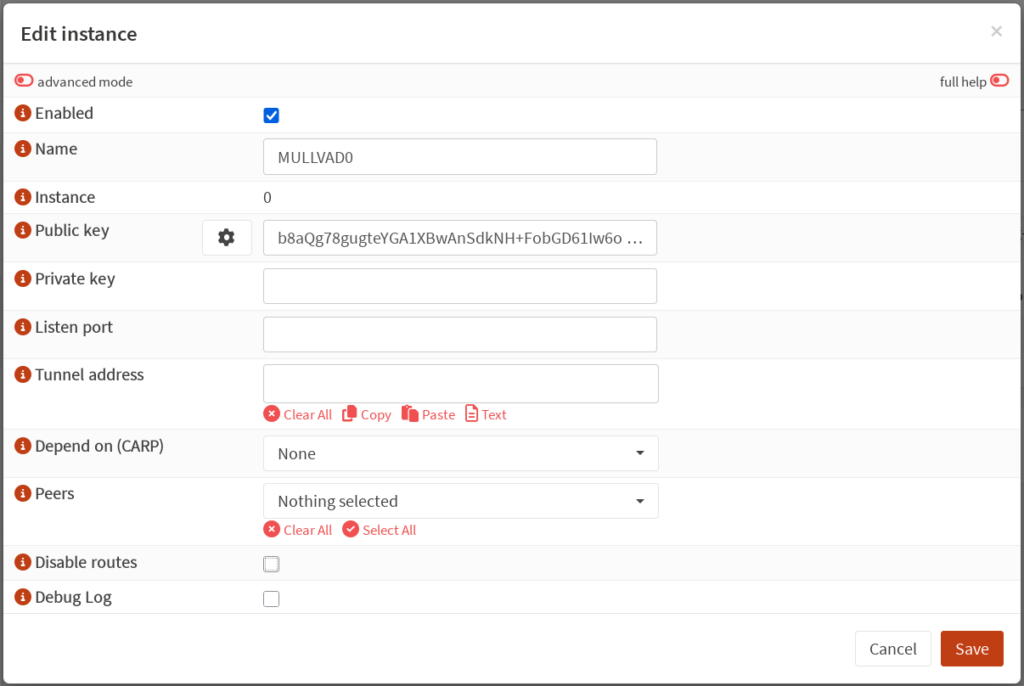
First, login to your OPNsense firewall and go to VPN: WireGuard: Instances. Add a new instance. Give the instance a name such as “MULLVAD0” or “WG0”. Click the gear icon next to the “Public key” field to generate a new keypair. The screenshot below omits my private key for self-evident reasons, but OPNsense will generate both parts of the keypair. Copy the resulting public key to your clipboard. You’ll use this to generate a new device in Mullvad’s website.
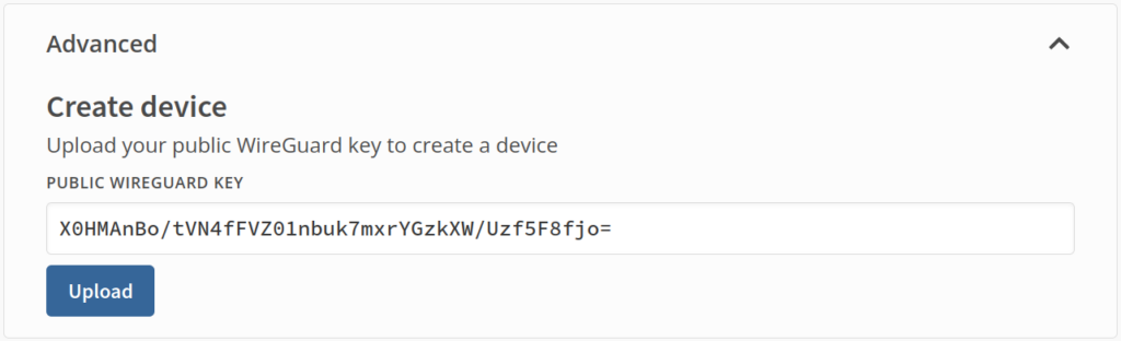
Login to your account on Mullvad’s website, and navigate to “Devices”, under the “Account Management” section. Scroll down to the bottom and expand “Advanced”. Paste the public key generated by OPNsense into the field and press “Upload” to create a new device.
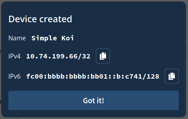
You should see a popup that has the name of your new device, as well as what IPv4 and IPv6 addresses to use for the interface. Copy the IPv4 and IPv6 addresses.
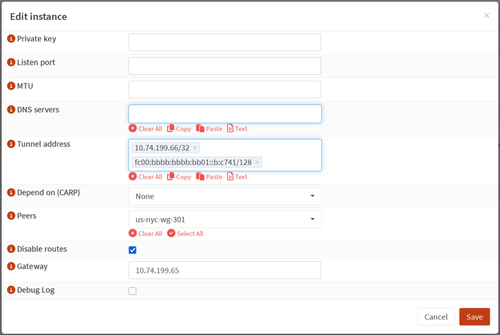
Return to your WireGuard instance configuration, and paste the IPv4 and IPv6 addresses generated by Mullvad into the “Tunnel address” field. Leave the “Listen port” field blank, as this instance will not be listening for connections. Tick the “Disable routes” box as we do not want OPNsense to create default routes for this interface. Enable “advanced mode” at the top of the new instance configuration, then in the “Gateway” field, enter the IPv4 address copied from Mullvad, but subtract one from the last octet. Mullvad instructed me to use an IPv4 address of 10.74.199.66, so for the “Gateway” field I will enter 10.74.199.65. OPNsense documentation has the following note regarding the value for Gateway:
The IP you choose for the Gateway is essentially arbitrary; pretty much any unique IP will do. The suggestion here is for convenience and to avoid conflicts
Once everything looks good, click “Save”, then click “Apply”.
Peer Configuration
Now it’s time to configure the peer. For this step, return to Mullvad’s website, scroll to the bottom, and select “Servers”. Alternatively, navigate directly to https://mullvad.net/servers. Select a desired endpoint for your tunnel. Choosing an endpoint that is nearer to you geographically will generally yield faster speeds than one which is far away, though some users might have privacy or content accessibility reasons for choosing an endpoint in a different location. For this setup, I will choose the us-nyc-wg-301 server. Copy the public key and IPv4 address for your desired server.
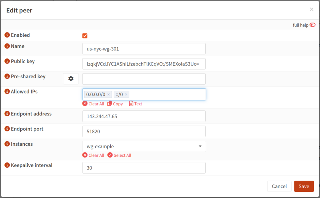
Return to OPNsense, then navigate to VPN: WireGuard: Peers and add a new peer. Paste the public key and IPv4 address copied from Mullvad’s website. Mullvad does not use pre-shared keys so leave this field blank. Give the peer a name. I like to set the name to the name of the server, for instance us-nyc-wg-301. Under “Allowed IPs” add 0.0.0.0/0 and ::/0. These respectively mean that all IPv4 and IPv6 destinations are eligible to be tunneled through this interface. Set the endpoint port to 51820. Under the “Instances” dropdown, select the WireGuard instance you created above. “Keepalive interval” can be left blank or set to a value in seconds, say 30. Click “Save”, then click “Apply”.
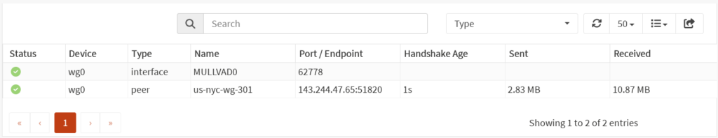
If “Enable WireGuard” is not selected, select it then click “Apply”. If already selected, toggle it (clicking “Apply” in between) to force the interface to be reset. Now, if you navigate to VPN: WireGuard: Status, you should see a green check mark next to your new interface, as well as the time since the last handshake and some other details.
Creating an Interface
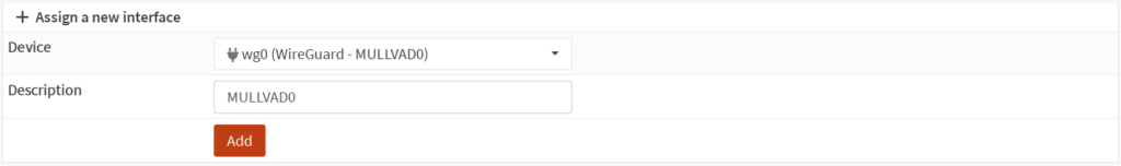
Navigate to Interfaces: Assignments. In the “Device” drop-down, select your new WireGuard instance. Give it a description if not pre-populated, then click “Add”.
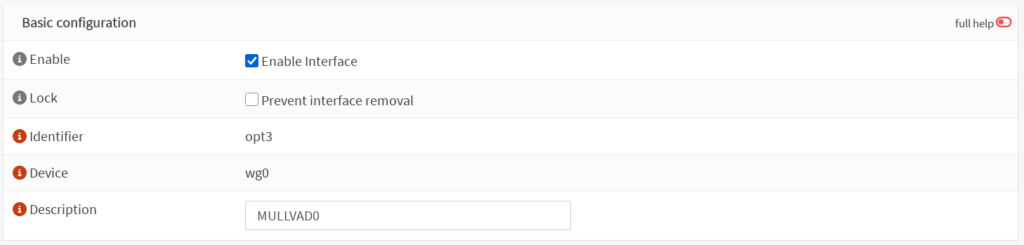
Now you should see a new interface in the “Interfaces” list with the name of your WireGuard instance. Select this new interface, tick “Enable Interface”, click “Save”, then click “Apply changes”. There is no need to further configure this interface.
Outbound Rules
Navigate to Firewall: NAT: Outbound. Ensure that either “Hybrid outbound NAT rule generation” or “Manual outbound NAT rule generation” is selected. Add a new outbound rule. Under the “Interface” field, select your WireGuard interface. Under “Source address”, select “LAN net”, or whichever network or alias you wish to tunnel through the VPN. Ensure the “Translation / target” field is set to “Interface address”.
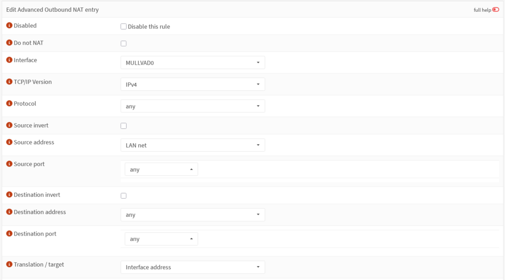
This rule takes care of network address translation for traffic from your LAN net private IP address to your tunnel address. Click “Save”, then click “Apply changes”.
Gateway
Next we need to create a Gateway for our tunnel. Navigate to System: Gateways: Configuration and add a new gateway. Give it a name, and select the interface created above in the “Interface” drop-down. In the “IP address” field, enter the IPv4 address you used for the “Gateway” field when creating the interface (IP address provided by Mullvad with one subtracted from the last octet). Select “Far Gateway”, and deselect “Disable Gateway Monitoring”. In the “Monitor IP” field, we need to select a different IP address as the gateway IP address is likely not going to respond to pings for reasons outlined above. You can select a public IP address that responds to pings like 1.1.1.1 or 8.8.8.8 here, or you can use Mullvad’s gateway of 10.64.0.1. If you have gateway monitoring enabled on multiple WAN interfaces, it is important that the monitor IP be unique for each gateway.
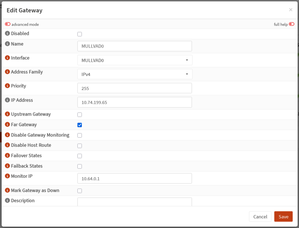
Click “Save”, then click “Apply”. Refresh the list of gateways after a moment, and you should see a green plug in the status field of your new gateway.
Firewall Rules
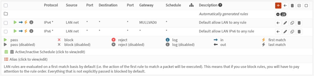
We now need to configure a firewall rule to route traffic from the LAN interface through the tunnel. Go to Firewall: Rules: LAN. You should already have some rules here. OPNsense creates default rules allowing all outbound IPv4 and IPv6 traffic. Edit the default rule for IPv4 traffic (this guide does not cover IPv6). In the Gateway dropdown, select the Gateway created above. Click “Save”, then click “Apply changes”.
Testing the Connection
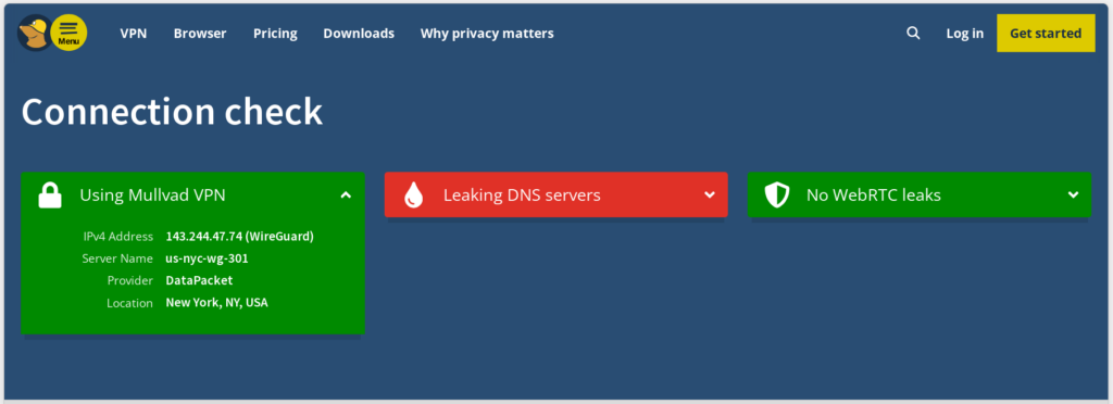
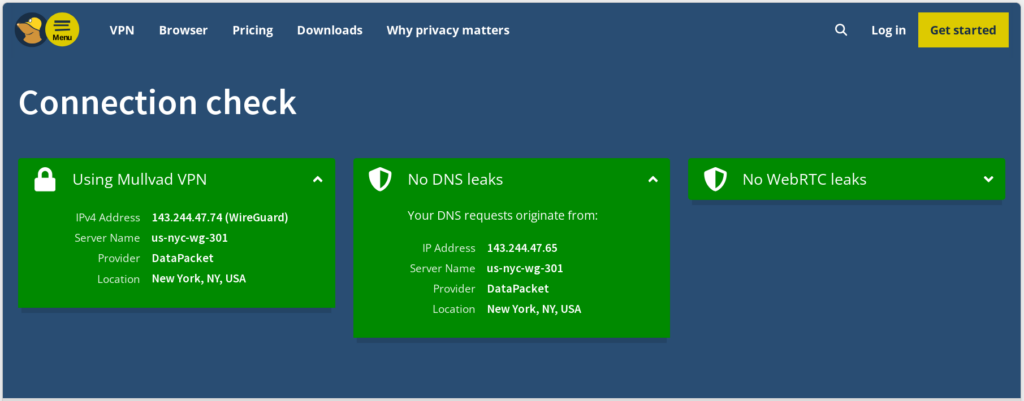
At this point traffic from your LAN interface should be routed via the Mullvad tunnel. You can now navigate to https://mullvad.net/check to test your connection. You should see that you are using Mullvad VPN. Mullvad will likely show you have leaking DNS servers. This is because we have not configured DNS requests to use the tunnel yet. We will address this next.
Tunneling DNS Requests
Domain name system (DNS) is how your devices get an IP address from a hostname. By default, OPNsense will just use your ISP’s DNS resolver to resolve hostnames. This is undesirable as it tells your ISP every website you visit even if all the traffic to that website goes through the Mullvad tunnel. To fix this we need to configure OPNsense to use one of Mullvad’s DNS resolvers via the tunnel. In addition to standard DNS resolvers, Mullvad also provides various blocklist DNS resolvers, a basic but effective way of blocking ads, trackers, social media, etc. You can find a list of all their DNS servers here. For this example, we will use 100.64.0.3 to block ads and trackers.
Navigate to Firewall: NAT: Port Forward, and add a new rule. In the “Interface” dropdown, select LAN. In the “Destination” dropdown, select “any”. In the “Destination port range” dropdown, select DNS. Under “Redirect target IP”, choose “Single host or network”, and enter 100.64.0.3. Click “Save”, then click “Apply changes”.
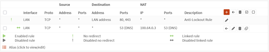
Adding a Killswitch
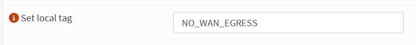
At this point, Mullvad’s connection check will likely still show leaking DNS resolvers. This is because traffic can still leave the firewall via the WAN interface. We will address this by adding a killswitch rule. Go to Firewall: Rules: LAN, and edit the IPv4 rule we configured the Gateway for earlier. Scroll down and expand the “Advanced features” section. Under “Set local tag” add “NO_WAN_EGRESS”. This tags all traffic matching this rule so we can create a rule to prevent it from leaving via the WAN interface. Click “Save”, then click “Apply changes”.
Now navigate to Firewall: Rules: WAN, and add a new rule. Under “Action” select “Block” or “Reject”. Under “Direction” select “out”. Under “TCP/IP Version” select “IPv4/IPv6”. Scroll to the bottom and expand the “Advanced features” section. Under “Match local tag” add “NO_WAN_EGRESS”. Give the rule a description such as “VPN killswitch”. Click “Save”, then click “Apply changes”.
At this point, if you refresh Mullvad’s connection check page, you should no longer see any DNS leaks. Additionally, if you disable your Mullvad Gateway in System: Gateways: Configuration, you should no longer have internet access.
Conclusion
Configuring OPNsense to provide a whole home VPN saves you the need for having multiple Mullvad accounts for more than five devices. It also allows you to tunnel traffic from IOT devices through Mullvad’s servers which you would otherwise not be able to do. As mentioned in the intro, using a VPN is a good first step to take in reclaiming your digital privacy, but I highly recommend reading Mullvad’s resources and resources from the Electronic Freedom Foundation to take it even further. In a future guide, I will explain how to setup dual VPN failover in OPNsense so that if your tunnel to one peer goes down, OPNsense will automatically failover to a backup peer.